Introduction
Architecture Drawing Art Techniques That Transform Design Concepts are essential tools for architects and designers. They allow you to visualize and communicate your ideas clearly to clients and builders. These drawings act as a blueprint, guiding construction and helping avoid errors.
In this article, you will learn the basics of architectural drawings, the importance of accuracy, types of views, and practical steps to create effective design sketches. Each chapter will focus on a specific area to help you improve your skills and understand the process behind transforming ideas into built structures.
What Are Architecture Drawings

Architecture drawings are visual documents that represent buildings, spaces, or structures at various stages of design and construction. They function like maps or blueprints, translating ideas into something tangible for everyone involved—from the architect to the builder, to the client. Without these drawings, it’s hard to picture a design fully or ensure it’s built as intended.
At their core, these drawings help clarify complex designs in simple, visual forms. They focus on details like dimensions, materials, and spatial relationships. I often find it interesting that while they’re technical, architecture drawings can also convey the personality of a project, sometimes expressing creativity more profoundly than words ever could.
The purpose is twofold: to communicate design intentions clearly and to guide the construction process step by step. Builders rely on them to understand what to build, how to build it, and where everything fits. Meanwhile, architects use these drawings to refine ideas and make sure designs are practical and safe. Without accurate drawings, confusion and mistakes multiply on site.
Purpose of Drawings in Architecture
Why do architects spend so much time creating drawings? Well, several reasons come to mind.
- They serve as a communication tool among all parties involved in a project, ensuring everyone is on the same page.
- Drawings provide a legal record of the design, often used in permits and contracts.
- They allow architects to experiment with and visualize design concepts before anything is built, which can save a lot of time and money.
- They guide builders on site, clarifying how components fit together and what materials to use.
It might seem straightforward, but these functions can overlap or create confusion if the drawings aren’t clear or detailed enough. I’ve seen cases where a poorly labeled floor plan caused delays that could have been avoided with a better drawing.
Types of Architectural Drawings
Architectural drawings come in different forms, each serving a specific purpose. Here are the most common types you’ll encounter:
- Floor Plans: These are horizontal slice views showing rooms, walls, doors, and windows. They help you understand the layout and flow of spaces.
- Sections: Imagine cutting through a building vertically to reveal the interior structure. Sections show heights, levels, and how spaces stack or connect.
- Elevations: These are straight-on views of a building’s exterior, outlining facade details, window placements, and materials.
There are more, but these three form the backbone of most architectural documentation. When I first learned about these, it felt like decoding a new language, but once you grasp their function, reading the drawings becomes less intimidating and more like storytelling.
How to Read Architecture Drawings

Interpreting Scale and Dimensions
Scale is the backbone of any architectural drawing. Without it, those neat lines and shapes would mean little. You’ll often find drawings at scales like 1:50 or 1:100. This means that 1 unit on the drawing equals 50 or 100 units in real life. But sometimes, the scale isn’t obvious right away—it might be tucked in a corner or written small. So, double-check before you start measuring.
Dimensions are how you translate what’s on paper into actual size. Look for dimension lines, usually thin and straight, capped with arrows. The numbers between tell you lengths, heights, or distances. But watch out—dimensions may only show distances between fixed points, not every little detail. So, reading between these lines is a bit of an art, not just a science.
Symbols and Annotations Explained
Symbols are like a secret code architects use to pack extra meaning into drawings. Doors often look like arcs showing their swing, windows are simple rectangles with lines, and stairs appear as a series of rectangles or parallel lines. Sometimes, these symbols change slightly depending on the architect or region, making it tricky at first.
Annotations include notes, abbreviations, or tags that clarify materials, finishes, or construction methods. For example, you might see “CL” for centerline or “Ø” to indicate diameter. These details are crucial. Skipping them can lead to misunderstandings, so pay attention to these little cues—they’re there to avoid confusion.
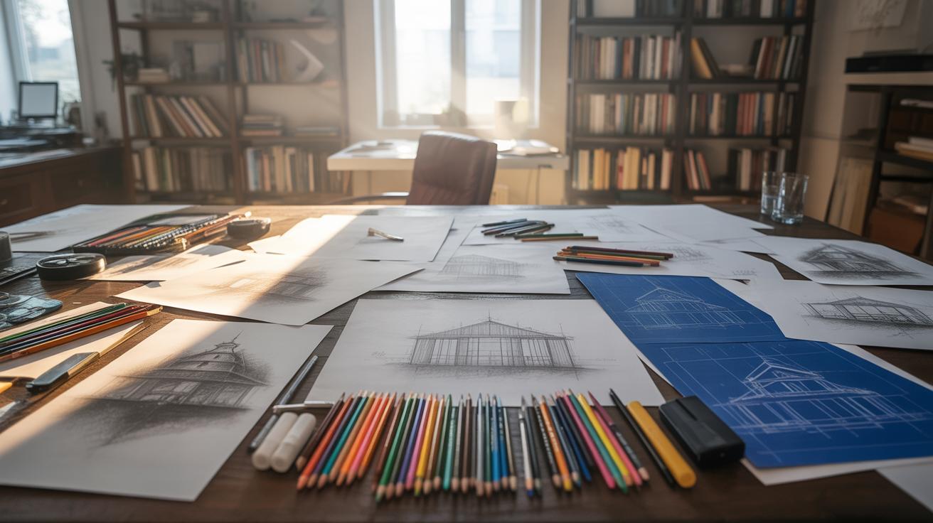
Tools for Creating Architecture Drawings

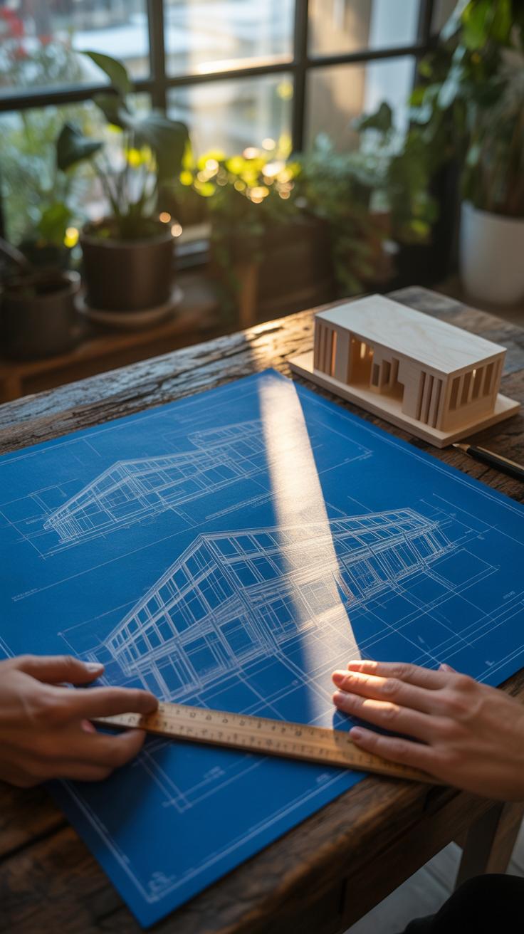
When it comes to making architecture drawings, the tools you use can shape the entire process. The craft has roots in manual techniques—those simple materials like pencils and paper that have been around for centuries. These old-school tools, though basic, still carry a charm and precision that many architects value deeply. There’s something about the grip of a well-worn pencil or the smooth glide of tracing paper that digital can’t quite replace.
For manual drawing, typical tools include:
- Pencils in various grades, from hard H to soft B, to control line weight and texture
- Rulers and T-squares, essential for straight lines and accurate measurements
- Tracing paper, which allows layering and easy corrections without starting over
- Drafting pens for sharp, permanent lines when the draft is finalized
On the flip side, digital methods now dominate much of architectural design. CAD software like AutoCAD or Revit offers precision and easy editing that manual methods struggle to match. They let you zoom in on details or adjust entire layouts quickly. But then, sometimes the endless options can feel overwhelming, and I wonder if the design’s spontaneity gets lost in all the clicking and dragging.
Some digital tools popular in architecture include:
- AutoCAD – standard for precise 2D drafting and documentation
- Revit – for 3D modeling and building information modeling (BIM)
- SketchUp – favored for rapid conceptual models and approachable interface
- ArchiCAD – combines modeling and drafting in an integrated platform

Each tool serves a different purpose and workflow. You might find yourself shifting between pencil sketches in early stages for freeform ideas, then moving to CAD software for detailed plans. Do you prefer the tactile connection of drawing by hand, or the flexibility of digital? It really depends on the project and your personal style. Maybe the best approach blends both worlds, letting you keep control but embrace efficiency where needed.
How to Start an Architectural Sketch

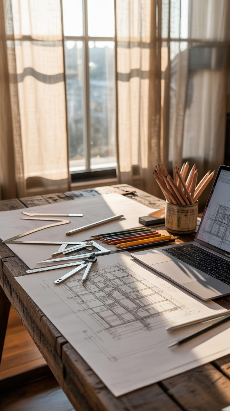
Setting Up Your Drawing Space
You don’t need a fancy studio to begin sketching architecture. What matters most is having a place where you can focus, with enough room to spread your tools. I find that a flat, uncluttered surface—like a sturdy desk or a table—works best. Natural light helps, but if that’s tricky, a bright desk lamp can do the trick.
Organizing your tools early makes a difference. Keep pencils, erasers, rulers, and sketch paper within easy reach. Sort them out so you’re not hunting when an idea strikes. Maybe use a small container or tray. It feels odd how something as simple as a clean space can spark better sketches—or so I’ve noticed.
Make sure your chair is comfortable but keeps you upright; slouching tends to mess with your lines. The last thing you want is an awkward posture that makes your hand shaky or your focus wander. That said, sometimes leaning back while staring at a blank page helps the ideas come—so it’s okay to be flexible here.
Basic Sketching Techniques
When you start sketching, begin by drawing simple shapes. Boxes, rectangles, and basic polygons form the backbone of most architectural ideas. I usually start with a rough outline of the building’s footprint—think about how the shape interacts with the space around it.

Use light, loose lines first. Pressing too hard might lock you into a shape before the idea fully forms. It’s like feeling your way around the design, not trying to capture it perfectly immediately. If you aren’t sure about proportions, sketch multiple versions side by side and compare.
For floor plans, start by marking main walls with simple parallel lines. Add doors and windows as breaks in these lines. You don’t need to detail everything right away. Focus on the flow—how someone might move through the space. It’s surprising how these simple steps often uncover challenges or opportunities you didn’t see before.
Try mixing freehand lines with quick measurements. You might use a ruler for straight edges but allow your hand to soften the overall feel. This balance keeps your sketch lively while staying clear enough to build on later.
Floor Plans Explained

A floor plan is basically a bird’s eye view of a building’s layout. It shows how spaces connect, where walls stand, and how rooms relate to one another—not in three dimensions, but as a clear, flat diagram. You could say it’s the blueprint of daily movement inside a home or office, helping everyone from builders to clients understand the spatial arrangement before anything is built. If you look closely, it tells a story about function and flow, though sometimes that story seems a bit rigid or, on the flip side, surprisingly open.

Drawing a floor plan clearly takes some patience. You want every line deliberate, every scale accurate enough so the drawing feels real, not just a rough sketch. Think of it as the foundation for everything else—miss something here and the whole design might wobble. And yet, some architects like to leave a little ambiguity in their initial floor plans, as if to invite interpretation or change.
Elements of a Floor Plan
There are key components you’ll see on nearly every floor plan. Understanding them helps you both read and draw these plans better.
- Walls: Usually drawn as parallel lines—sometimes thick, sometimes thin—to show structural or partition walls. They define rooms and corridors but don’t always indicate thickness precisely.
- Doors: Represented by gaps in walls with an arc showing the path they swing. This arc is crucial; it tells how a door opens and whether it might block anything nearby.
- Windows: Shown as breaks or thinner lines within walls. They often include small marks or lines to suggest frames, but it’s tricky—sometimes window symbols look nearly identical to open doors at first glance.
- Fixtures: Items like sinks, toilets, or kitchen counters appear as simple shapes or symbols. Their presence hints at a room’s function but can feel a tad abstract if you’re not used to reading these signs.
- Dimensions: Not always present in basic plans, but when added, these lines and numbers clarify space sizes. They guide builders and help detect errors early.
Drawing a Basic Floor Plan
Start simple. Maybe a small room or studio. Here’s a way to get your hands moving:
- Sketch the outline first—draw a rectangle or square lightly to mark the room’s boundaries.
- Add walls inside if you want to divide the space. Use two parallel lines for each wall to represent thickness. Try to keep your scale consistent—say each centimeter stands for one foot.
- Mark door openings next. Make sure to indicate the swing arc so others can visualize how the door works.
- Place windows along walls. These should break the wall lines to represent openness. Varying their size can show differences but don’t overcomplicate it—clarity comes first.
- Include basic furniture or fixtures if you feel it helps—like a bed or kitchen sink—to give context to room functions.
- Use a ruler or straightedge. Even freehand lines should be neat enough to read. You can erase and redraw—as many times as needed—to get it right, though the process can feel a bit frustrating at times.
It might seem straightforward, but every plan reflects choices and compromises. You might wonder if a window’s placement optimizes light or if a door’s swing impedes movement. Those small details matter more than they appear—and shaping a good floor plan is part art, part puzzle-solving. Give it a try and see what you notice differently in spaces around you.
Using Sections and Elevations
What Are Sections in Architecture

Sections in architectural drawings slice through a building like a knife, revealing what’s hidden inside. They expose walls, floors, and structural elements that plans or elevations alone cannot show plainly. When you think about it, sections help you understand how spaces relate vertically—room heights, staircases, and internal arrangements come to life here.
Creating a section involves deciding where to ‘cut’ through the design, usually through important parts like corridors or stairways. This cut line is then translated into a detailed drawing showing materials, thicknesses, and spatial order. Sections often feel more technical, but they also tell a story—about how people might move through or experience the building. I remember the first time I drafted a section; it suddenly made the whole project much clearer, which surprised me given how abstract plans seemed before.
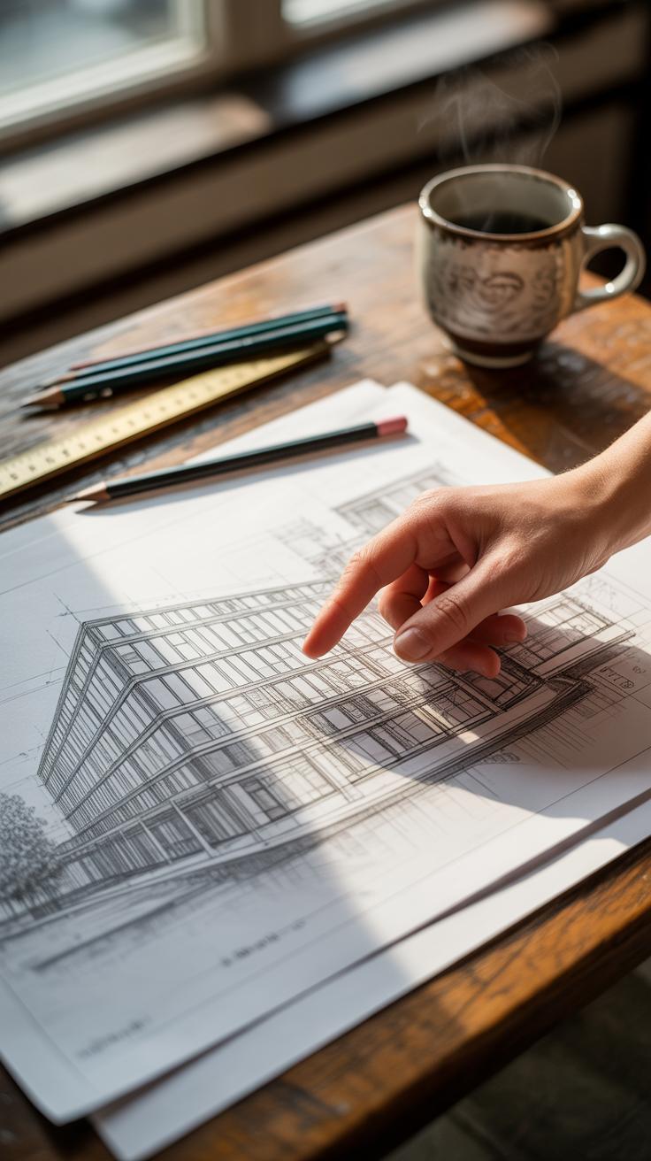
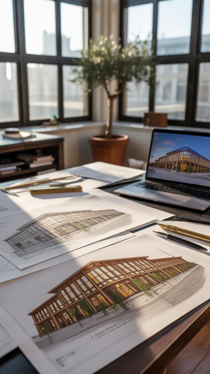
Understanding Elevations
Elevations present the exterior faces of a building—it’s like a direct gaze at the walls, windows, doors, and roofline. Unlike sections that peek inside, elevations show how the building looks from the outside, often in true scale and detail. These drawings don’t just show façade design; they also help you assess proportions, materials, and architectural style.
When drafting elevations, you capture the building’s outward identity, which is crucial when you want to communicate appearance and relationship to context. I think elevations serve as a bridge between technical drawings and visual impressions. You get to see how elements align—or don’t—with each other on a flat plane, which sometimes reveals unexpected asymmetries or charming quirks that plans can’t highlight.
Common Mistakes to Avoid


When working on architectural drawings, some errors tend to sneak in more than you’d expect. One of the most frequent—and frustrating—issues comes from errors in scaling. You might think your measurements are spot on, but a tiny slip can throw off the entire plan. For example, drawing a door at the wrong scale can make it unusable in reality or create confusion later. To avoid this, double-check your scale frequently, keep a ruler or scale tool handy, and don’t trust your eyes alone. Measures can feel straightforward but often deceive.
Line quality is another stumbling block. Rough, inconsistent lines quickly turn a drawing into a confusing mess. There’s something about clean, deliberate lines that gives a drawing clarity and purpose. I remember struggling to read some early sketches of mine, all because I wasn’t careful with line weight or precision. Use sharp pencils or pens, practice steady strokes, and if possible, incorporate line variation to show different elements clearly. It’s about more than just looking neat—it affects how someone reads and understands your design.
Ask yourself: are my lines communicating the right message? Are the scaled dimensions believable at a glance? These questions keep you alert and can prevent simple mistakes that skew your entire project.
Compare Manual and Digital Drawing

Manual architectural drawing feels very different from working in a digital environment. When you draw by hand, there’s an immediate physical connection. The pencil or pen responds directly to your touch. That tactile feedback can spark creativity in ways that a mouse might not. Sketching rough outlines or shading by hand lets you experiment spontaneously. If you’re like me, you sometimes discover ideas just by letting your hand wander. On the downside, manual drawings demand patience and skill to keep things precise, and redrawing mistakes can be tedious.
Digital CAD drawings bring accuracy that’s tough to match manually. The tools help you snap to grids, measure precisely, and edit without starting over. Flexibility is another perk: layers let you toggle details on and off, and you can easily duplicate or tweak elements. But there’s a catch. Sometimes the process feels detached. You may lose that intuitive flow you get with hand-drawing. Also, digital tools require learning curves; not everyone feels comfortable diving in immediately.
Both methods have their quirks and perks. Maybe the best approach is knowing when to rely on instinct and when to depend on precision. Which do you lean toward when shaping your earliest design ideas? Could blending the two offer the best of both worlds?
Advantages of Manual Drawing
Hand-drawing makes you slow down and engage with your design in a different way. It encourages you to visualize form and space physically. You can adjust lines freely with a quick eraser swipe or add texture intuitively. Sketching can also reveal flaws or inspire new paths you might miss in CAD’s rigid interface.
Many architects find that manual drawing builds foundational skills that digital tools alone don’t teach. You learn to read space, proportion, and scale without relying on software aids. There’s also a certain authenticity in pencil marks that connect you directly to your conceptual process. Even if the final is digital, those initial sketches often remain invaluable.
Benefits of Digital CAD Tools
Accuracy stands out immediately. CAD tools let you create exact dimensions, ensuring your design fits construction requirements strictly. Edits that might take minutes or hours by hand happen in seconds here. You can layer plans, elevations, and sections for comprehensive views without redrawing each part.
Flexibility is another key advantage. Digital files make sharing, storing, and revising designs effortless. You can simulate lighting, materials, or even structural stresses with specialized extensions. It makes the design process less error-prone, but sometimes it might feel less personal—like your design is one of many versions stored somewhere in a cloud rather than a distinct creation.
Ultimately, both manual and CAD drawings shape your design differently. Maybe it depends on what stage you’re at, or the feel you want in expressing your architectural vision.
Checklist for Finalizing Drawings
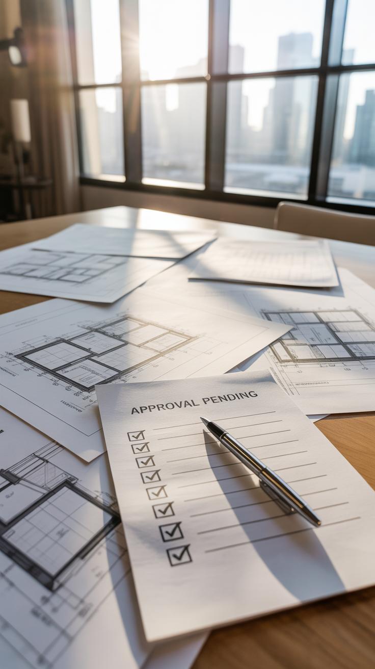
Before you call an architectural drawing finished, there’s a quiet moment where you almost hesitate — a pause to ask, “Did I cover everything?” That pause is valuable. To help with that, here’s a checklist that you can run through quickly, almost like a mental reset.
First, check your scales. Make sure every element truly reflects the scale you set out to use. It’s easy to overlook tiny inconsistencies that, when built, can cause headaches. For example, a window drawn slightly off scale can throw off not just measurements but proportions and feel.
Next, focus on the details. Are all details sharp and accurate? Details aren’t just decoration; they communicate how parts connect. If something looks vague or off, your builder might hesitate or guess. That guesswork rarely turns out well.
Annotations need a careful review. You might think your notes are clear because you wrote them, but can someone else quickly understand them? Unclear or missing labels could obscure intent. Imagine flipping through your drawing, and something critical is just a cryptic note—or worse, no note at all. That’s a problem that slows down projects.
Try to read your labels as if the project were unfamiliar to you. Do measurements stand out? Is every material callout precise? If you pause anywhere, mark it for revision.
Lastly, take a moment to consider the whole drawing’s flow. Does everything “fit” visually? Sometimes drawings are accurate but cluttered or confusing to follow. Maybe you need to simplify or adjust line weights.
So, would you rather rush and fix mistakes later, or take this extra moment now? This checklist isn’t just a step; it’s a chance to catch those borderline errors that slip in unnoticed.
Case Study Architecture Drawing
Concept Sketch to Detailed Plan
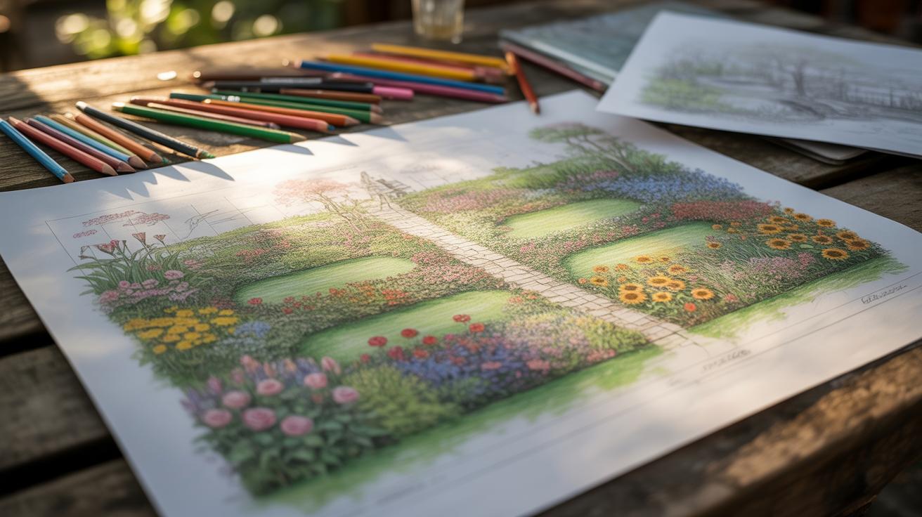
Imagine starting with a rough sketch—just a simple outline of a small house on a piece of scrap paper. You sketch a square for the building footprint, a triangle for the roof, and mark a few rectangles for windows and doors. This early stage is loose, almost messy, but it captures the core idea: where the walls go, how the space feels.
From there, you begin refining. Lines become straighter, proportions measured, and details added—stairs, room divisions, and exterior elements like pathways. You switch from pencil to technical pens, maybe drafting software if you prefer, but the essence remains a gradual, step-by-step build-up. The initial notion guides adjustments, but surprises pop up: maybe a window shifts to catch better light, or a wall moves for better flow.
Lessons from the Example
This process reminds you that architecture drawing is about balancing freedom with precision. Starting rough helps you explore ideas quickly without obsessing over perfection. Later, precision translates that vision into a usable plan. Sketching brings ideas out without judgement, then detailed drawings test feasibility.
Key takeaways?
- Don’t fear messy sketches—they’re the seeds of clarity.
- Incremental refinement avoids overwhelming complexity.
- Flexibility at the early stage encourages design evolution.
- Details matter, but only after the main layout works.
- Use drawing tools that suit your current step, not a one-size-fits-all approach.
Would jumping straight to detailed plans ever really work? Maybe not, since early messiness lets you uncover what matters. So, allow your drawings room to breathe before locking them down.
Conclusions
Architecture drawing brings clarity and precision to your design concepts. By mastering drawing techniques, you enhance your ability to communicate ideas and achieve better results in your projects. These drawings serve as essential guides for constructing buildings according to your vision.
Working step-by-step, focusing on key views, scales, and tools, you can improve your drawings and bring your architectural ideas to life. Keep practicing these techniques and refine your skills to see your concepts develop into tangible designs.