Core Principles of Architectural Drawing
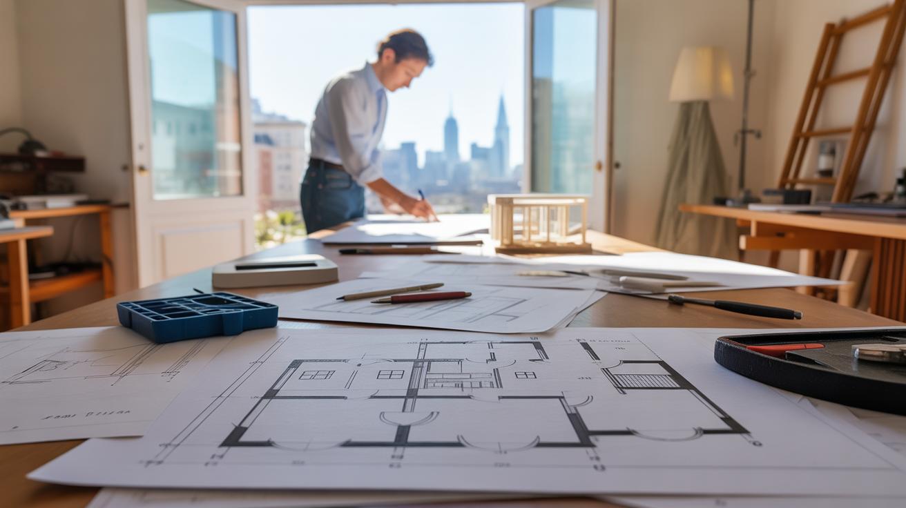
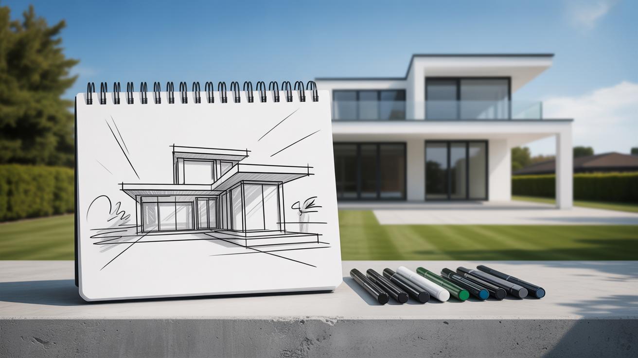
Architectural drawing is a critical skill for architects and designers. It is not just about creating visuals but about communicating ideas clearly and accurately. This article explores the core principles of engaging architectural drawing practices that can help you develop strong, effective designs.
You will learn about the fundamental elements, different views, scales, and techniques that make architectural drawings both informative and appealing. These principles serve as the foundation for transforming ideas into tangible plans that others can understand and use. Mastering these basics will improve your architectural work and help you convey your vision better.
Purpose and Importance of Architectural Drawings
Architectural drawings exist for several reasons, but at the core, they are tools meant to make something complex clearer. When architects create drawings, they’re not just sketching lines—they’re trying to capture an evolving idea, something that’s partly imagined and partly tangible. They help you see a building before it’s built. This can sometimes feel like a kind of magic, but really, it’s about communication.
These drawings serve to communicate design ideas, yes, but they also act as records. They hold details—sometimes little changes made halfway through construction, or decisions about materials. You could say they are a kind of memory for the project, a storehouse of knowledge that can be revisited. If something goes wrong, builders and architects return to these drawings to understand what was meant, what changed, what stayed the same.

On a practical level, drawings are necessary guides for construction teams. They provide clear instructions—dimensions, materials, junctions, and more—that you can’t just guess at. Without these visual guides, construction would be far less predictable. I recall one project where a missing detail on a drawing caused a costly delay; it was a stark reminder that these documents are anything but optional. They connect ideas to reality.
Communicating Design Ideas
When you look at an architectural drawing, you’re seeing more than just walls and windows. The drawings express a vision. They translate abstract concepts into something you can understand and discuss. For clients, these visuals are often the first glimpse into what their future space might feel like. And for builders, drawings spell out the intentions behind every shape and line. Without them, communication would fall apart.
Imagine trying to explain a building only in words—confusing, right? Drawings bridge that gap. They allow feedback, questions, and adjustments. Sometimes, an architect’s sketch sparks a change because it reveals something unexpected—a light pattern or a new use of space. That conversation lives in the drawings.
Supporting Construction and Record Keeping
Construction crews rely on drawings as their road map. They tell them where to place each component, from the foundation to the tiniest fixtures. In this way, drawings reduce uncertainty and errors. They also document progress and modifications. Often, what you see on site varies from original plans, and updated drawings act as official records of those changes.
This record aspect matters beyond the build. Owners and future architects refer to these drawings for maintenance, renovations, or expansions. It’s a bit like a logbook that travels through time, preserving knowledge. Even decades later, these drawings might be the only source explaining why a wall exists or what material was chosen. At times, I’ve seen this archival role go underappreciated, but it’s crucial.
Standard Views in Architectural Drawing

When you look at architectural drawings, you often see a few key views repeated: floor plans, sections, and elevations. Each of these is like a different lens on the same building, revealing unique pieces of information.
Floor plans lay out the arrangement of rooms, doors, and walls from a bird’s-eye view. This is where you get a clear sense of how people will move through the space. It’s not just about walls and furniture, but about relationships between rooms and flow.
Sections slice vertically through the building, showing what’s inside the walls or above ceilings, often things you can’t see otherwise. These are essential for understanding structure, materials, and interior height differences.
Elevations display each exterior face of the building, offering a straight-on view of windows, doors, and facade details. They help visualize the building’s look and its interaction with surroundings.

Each view serves a specific function but ties together into a fuller understanding. You might ask—can’t a single drawing show everything? Not really. Separating these views clarifies complex details without clutter.
Floor Plans and Their Role
A floor plan is basically a top-down map of a building’s layout. Imagine cutting through at about waist height and peering down—that’s what a floor plan shows.
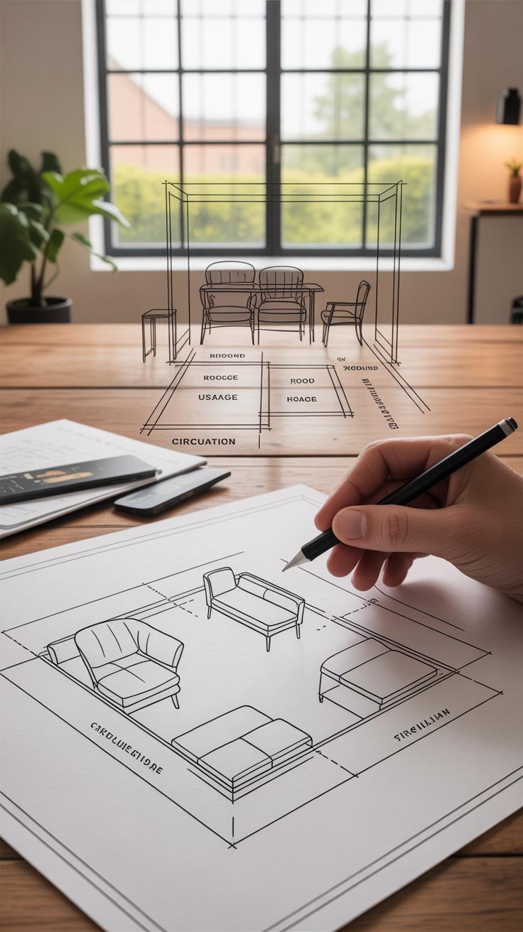
This view details room sizes, the positions of walls, doors, and windows, and often furniture. But it goes beyond mere placement; floor plans help you grasp circulation paths, form zones of activity, and identify constraints.
For example, does that narrow hallway make sense? Or is there enough open space in the living area? These kinds of questions start here.
Sections and Elevations
Section drawings are like vertical slices. By “cutting” through, architects expose hidden features—floor thickness, stair profiles, ceiling heights, and how different levels connect. I’ve found these particularly useful to catch issues early, like awkward headroom or unclear material transitions.

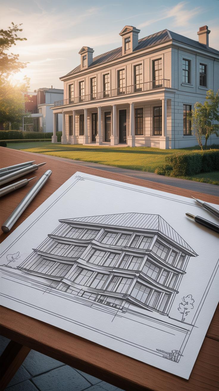
On the other hand, elevations focus on exteriors. They reveal height, window style, and facade rhythm—all visible elements shaping how the building presents itself. You might think elevations are simply “pretty,” but they’re more: they’re critical for understanding proportions and external context.
In essence, all three views—floor plans, sections, and elevations—work together. Each fills gaps left by the others, and together, they give a comprehensive picture that guides every construction decision.
Understanding Scale and Measurement
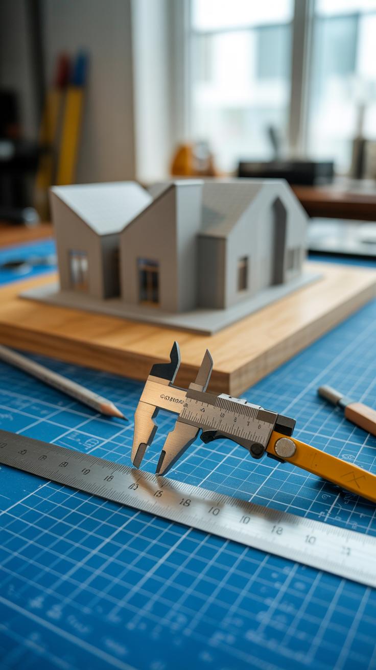
Scale in architectural drawings is how real-world dimensions shrink down to fit on paper. Without it, a design would be just a vague sketch, lacking precise meaning. Scale lets you represent large buildings or tiny details in a manageable size, so everything fits and means something.
Typical scales you’ll see include 1:100 for general floor plans, 1:50 for interior layouts, and even 1:20 or 1:10 when focusing on details. Using a scale ruler or a digital tool helps in reading and creating these drawings accurately. I remember once struggling to interpret a drawing where the scale wasn’t clear; it threw off the whole measurement process unexpectedly.
Choosing the right scale depends on what you need—big, overall views or fine details. For example:
- Site plans usually use smaller scales like 1:500 or 1:200 because you need the whole area.
- Floor plans and elevations often use 1:100 or 1:50 for clearer readability.
- Details require bigger scales, such as 1:20, so you can see the specifics.
It’s tempting to always grab the same scale, but the choice changes with the drawing’s purpose, or else you risk losing clarity or misrepresenting size.
Reading scaled drawings properly means focusing on the dimension lines and numbers—they tell you the exact measurements. But you can’t just eyeball it; you have to use scaling tools to translate those figures correctly. In construction, an error of even a few millimeters can cause headaches, delays, or worse. Precise measurement isn’t just about neatness—it can make the difference between a successful build or not.
Drawing Conventions and Symbols
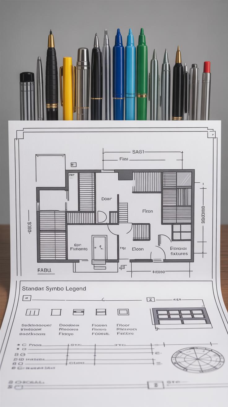
Architectural drawings rely heavily on a shared language of conventions and symbols to keep things clear. Without these, a drawing quickly becomes confusing—everyone guessing what lines and marks might mean. These conventions work like a silent agreement among architects, engineers, and builders. For example, thick continuous lines typically represent walls, while dashed lines might indicate elements hidden above or below the plane.
Common symbols in architectural drawings give quick insights into features without cluttering the page. Doors often appear as arcs showing their swing direction. Windows are usually drawn as thinner rectangles set within wall lines. Materials—like concrete, brick, or wood—use specific hatch patterns; a brick might be crosshatched in one way, while wood grain lines differ. You’ll find these symbols repeated in most drawings, so recognizing them helps you read plans faster, even if styles vary slightly from one architect to another.
Annotations and notes play a subtle but crucial role, often overlooked. They add context that symbols alone can’t deliver. Think of labels specifying door types or material finishes. Sometimes notes will instruct on construction methods or point out exceptions. While symbols convey form, annotations provide meaning. Without them, important details risk going unnoticed, leading to errors later in the building process. When you’re reading a drawing, it’s worth pausing to absorb these notes—they’re not just filler.
Would you agree, then, that mastering drawing conventions is more than memorizing symbols? It’s about understanding the conversation architects have with builders through sketches and legends. Learning this language might seem tedious but it’s essential for precision—and frankly, I think skipping it just adds unnecessary headaches.
Traditional vs Modern Drawing Techniques
Manual Drawing Practices
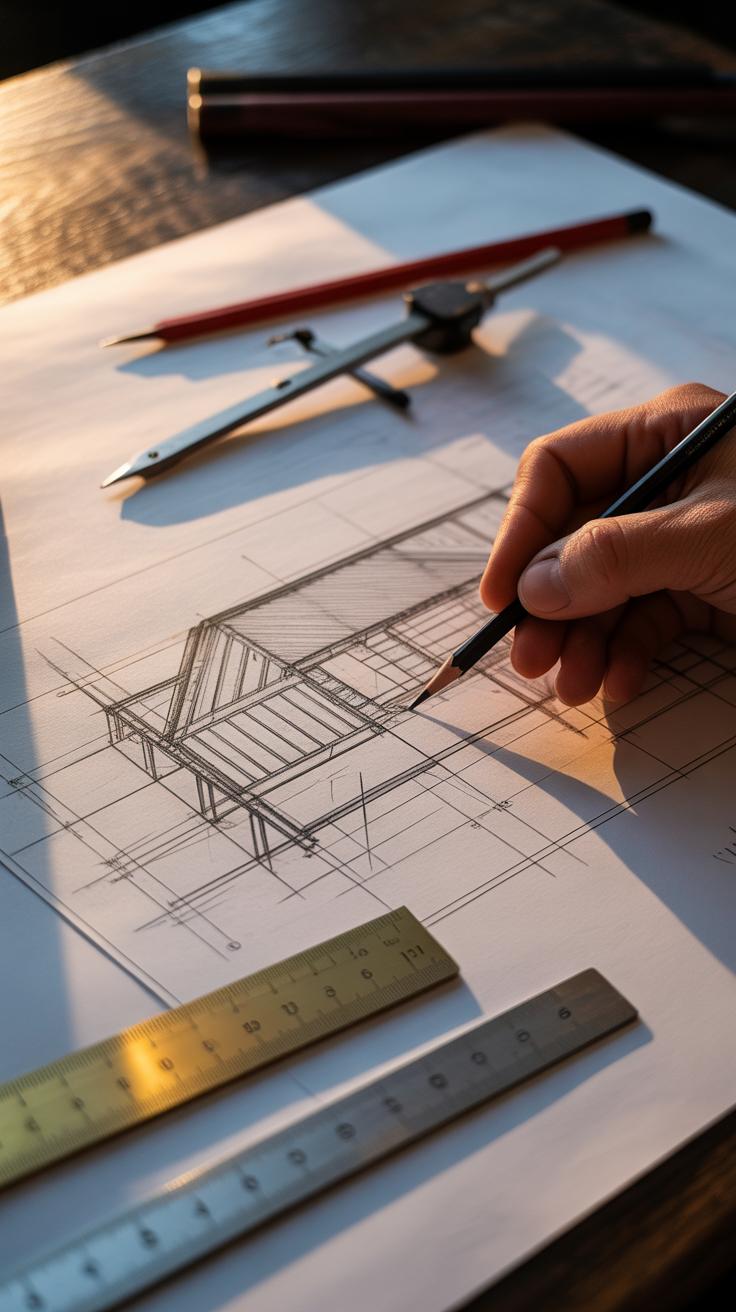
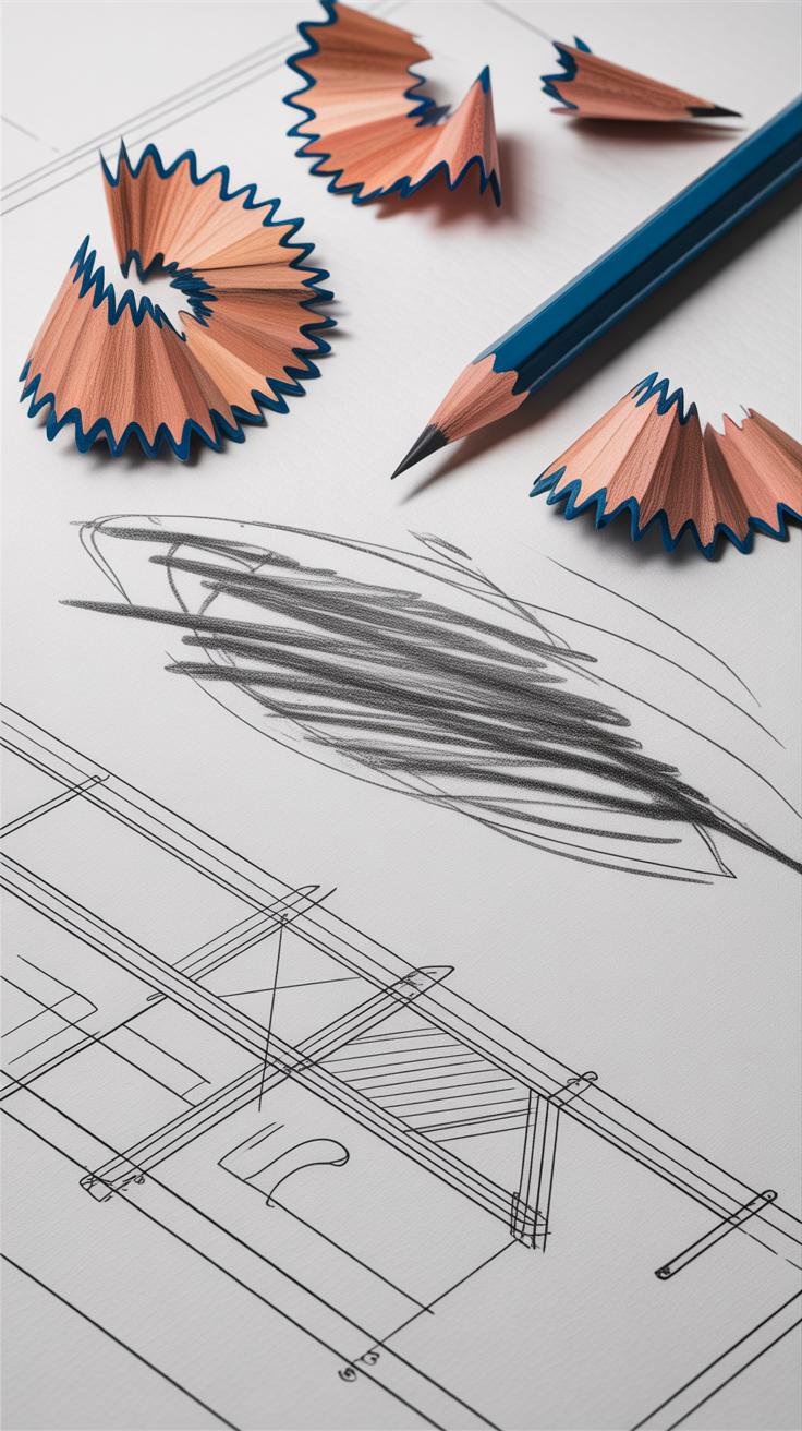
Working with pencils, pens, and tracing paper creates a distinct connection between the hand and the design. You feel every line, pressure, and hesitation. These tools allow subtle variations that digital doesn’t always capture. For example, a harder pencil can create fine detail, while a softer one adds depth with shading—something you don’t get by just clicking a button.
Tracing paper is often used to layer ideas, enabling architects to build complexity without losing sight of the basics beneath. It encourages a slower, more deliberate process. Yet, this slowness might frustrate when deadlines press. Mistakes mean erasing or starting anew, which can be painful but sometimes leads to unexpected creative sparks.

Still, reliance on manual tools often limits quick changes. You can’t easily replicate or share sketches with precision. The tactile nature is appealing, but also, well, it’s less flexible when you need to adjust details repeatedly or coordinate with others across distances.
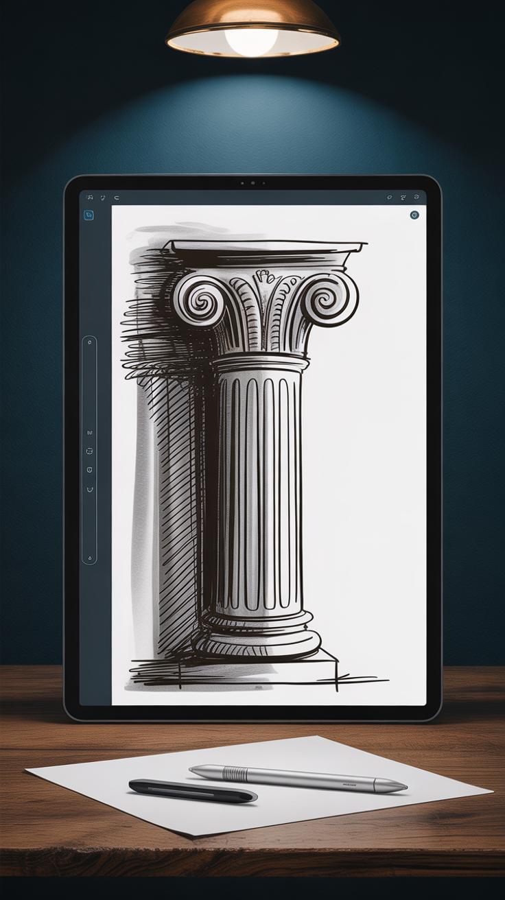
Digital Drawing and CAD
CAD software fundamentally changes what you can do with architectural drawings. Layers and templates let you work faster, and it’s much easier to edit mistakes without feeling like you’re ruining a page. Tools for 3D modeling or rendering give a fuller sense of space, which paper sketches simply can’t provide.
That said, digital drawing sometimes feels… detached. The physicality of pencil on paper is missing, and that may affect your creative rhythm. Plus, not all designs translate well through a mouse and keyboard—some subtle ideas get lost or simplified. Learning CAD can be a hurdle, especially for those used to traditional methods, and software updates mean constantly adapting.
Coordination and sharing become more straightforward with digital files, but the precision demands can be unforgiving. Small errors are visible, and sometimes the digital world pushes you to refine endlessly, perhaps losing the raw energy that early sketches hold. Do you prefer speed and polish, or the rough texture of a hand-drawn line? It’s a question you might wrestle with, projects after projects.
Creating Effective Floor Plans
Layout and Space Planning
When arranging rooms on a floor plan, think about how people will move through the space. You want the flow to feel natural but also purposeful. Often, designers place public spaces like living rooms or kitchens near the entrance to welcome guests—though sometimes it makes sense to tuck these areas away for privacy. Bedrooms usually appear in quieter zones, but that isn’t a hard rule.

Consider the purpose behind each room. If you’re designing for a family, maybe bedrooms cluster together with shared bathrooms nearby. If it’s an office layout, separate work areas to reduce distractions. Try to avoid layouts that force people to pass through one room to access another—unless that’s the intention. Sometimes, open floor plans provide flexibility but can also dilute the sense of defined space. Balancing privacy and connection can be tricky.
- Place rooms based on user habits and needs.
- Plan circulation paths clearly to prevent awkward bottlenecks.
- Think about sunlight exposure—daylight shapes how spaces feel.
- Group related functions—like kitchen and dining—for ease.
- Don’t forget potential furniture placement; it affects room size.
Including Details and Dimensions
Dimensions give your floor plan meaning. Adding clear measurements helps anyone reading the plan—whether a builder or client—grasp scale and proportion. I usually find it useful to measure room widths, lengths, and key distances like hallway widths or door clearances.
Details matter, but less can sometimes be more. Mark doors and windows clearly, defining how they open and where. Show built-in fixtures like cabinets or appliances, since they affect space use. Including symbols for stairs, columns, or structural walls helps avoid later confusion. You might hesitate about what to include, but aim for enough detail that someone could understand the layout with some imagination yet without needing a second drawing.
- Label all rooms consistently.
- Show wall thickness—this impacts furniture and space perception.
- Dimension critical elements, especially in tight areas.
- Use simple, standardized symbols for common features.
- Highlight circulation elements like door swings and corridor widths.
Designing floor plans isn’t just about drawing shapes; it’s about predicting how people live, work, and interact in space. Sometimes a small shift in room placement changes everything. If you’re unsure, try sketching multiple versions. After all, clarity in floor plans comes from considering not only what’s on paper but how it translates to real life.
Using Sections and Elevations to Show Building Details
Floor plans do a solid job showing the layout, but they leave out so much that you only really grasp once you see a section or elevation. Sections slice through the building—imagining a vertical cut straight through walls and rooms—making the inside visible. They reveal how floors relate to one another, the thickness of walls, and how structural elements like beams or columns sit within the space. It’s like peeking under the hood of a car after just seeing its outline.
Elevations, on the other hand, focus on the building’s face. They show what you would see standing in front of it—details of windows, doors, surface textures, even shadows cast by projecting elements. Elevations tell you about the style and character much more clearly than floor plans ever could. They express whether a building feels heavy or light, modern or traditional.
Using sections and elevations together fills gaps left by the plan. They help you understand both how a building works inside and how it speaks to the outside world. This dual insight is essential, especially when you want to communicate material choices, structural ideas, or design intent more fully.
Drawing Building Sections
When drawing sections, you essentially cut through the building—imagine slicing straight down a cake. This vertical slice lets you explore what’s inside walls and floors, relationships between rooms, and things you’d miss from above. How thick are the walls? Where do stairs land? Is there a mezzanine? These questions find answers in the section.
Start by choosing a cut line through crucial parts: spaces with complex relationships or where materials change. Draw the section with clear layers, showing structure like columns, beams, or slabs. Don’t forget to indicate openings like windows or doors within the section’s plane. Including furniture or human figures can help give a sense of scale—a little detail but one that often makes a section feel more relatable.
Sections require some practice. At first, it might seem like you’re drawing a confusing jumble, but over time you’ll get a sense of what to show and how much detail is enough. I’ve found that even simple sections can tell a powerful story if arranged thoughtfully.
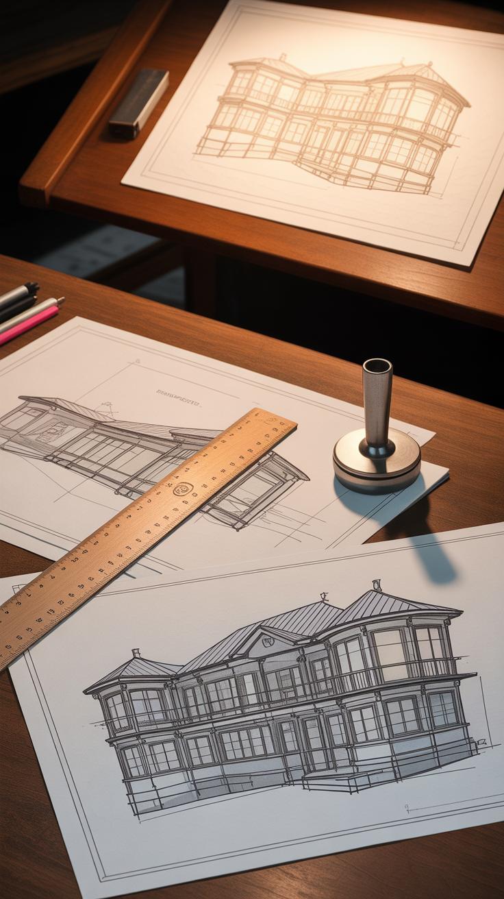
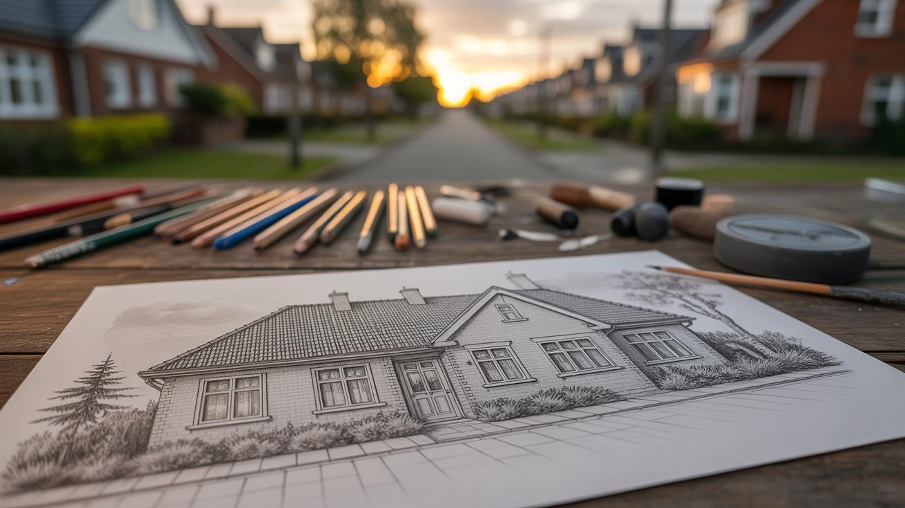
Designing Elevations
Elevations are your chance to depict a building’s character through its external appearance. When drawing elevations, focus on showing all visible surfaces, textures, and architectural features. This means paying attention to window styles, door placements, rooflines, and façade materials—each one contributes to the overall feel of the building.
Keep the scale consistent, and don’t shy away from highlighting small details like trims or moldings if they impact the design’s identity. Shadows and depth are tricky here but give life to the flat drawing. Sometimes, subtle hatching or shading can hint at material differences without overcomplicating the image.
Try to think about how your elevation talks to its environment. Is it a clean, minimal surface or an intricate, decorative façade? Your drawing should communicate that. Oddly enough, sometimes less detail brings out the design better—especially when the style is restrained.
Tips for Improving Your Architectural Drawings
Cleanliness in architectural drawings isn’t just about looks—it greatly affects how easily others can understand your work. Keeping lines crisp and deliberate helps avoid confusion. Sometimes, it’s tempting to rush or sketch loosely, but careful line work creates a clearer narrative of your design.
Labels should never be an afterthought. Clear, consistent annotations guide anyone reading your drawing through the intent behind each space and detail. A simple, well-placed note can prevent hours of miscommunication later on.
Organization also means layering information smartly. Separate elements on different sheets or layers to reduce clutter. That way, your drawings stay readable even as complexity grows. It may feel tedious at times, but the payoff in clarity is worth it.
Practice remains the cornerstone of improvement. Drawing often, even outside project deadlines, helps you develop steadiness and confidence. Revisit old sketches and notice where your line quality or proportions could be sharper. It’s a slow climb—there’s no overnight fix—but persistent effort leads to visible progress.
Are you sometimes frustrated by drawings that don’t exactly match your vision? If so, try breaking down your subject into smaller parts and drawing those repeatedly. Focus on tricky angles or details until they feel natural. Or study how others approach similar forms and compare their methods with yours.
Using Architectural Drawings to Communicate Your Vision
Architectural drawings do more than just show a building’s shape — they tell your story. When your drawings are clear and intentional, they become a bridge between your ideas and the people who bring those ideas to life. Clients see what you imagine before the first brick is laid, and builders get a map for their work, reducing guesswork and mistakes.
Think about moments when a project’s direction changed because of a drawing that didn’t quite capture the design intent. Would a more precise drawing have prevented hesitation? Probably. A well-done drawing can clear up doubts quickly, helping every decision feel grounded. It gives you, and everyone else, a concrete reference in a sometimes abstract process.
Clarifying Design Intent
Drawings work as your voice when words fall short. They detail materials, scale, and spatial relationships, making your vision less open to interpretation. Your clients rely on these drawings to understand what to expect — which can ease their concerns and build trust.
During project development, these visuals guide choices. Imagine negotiating between competing ideas about layout or structure. If your drawings spell out the intent, it’s easier to know which changes support the vision and which might stray from it. So, rather than endless meetings, decisions become more focused.
Collaborating Through Drawings
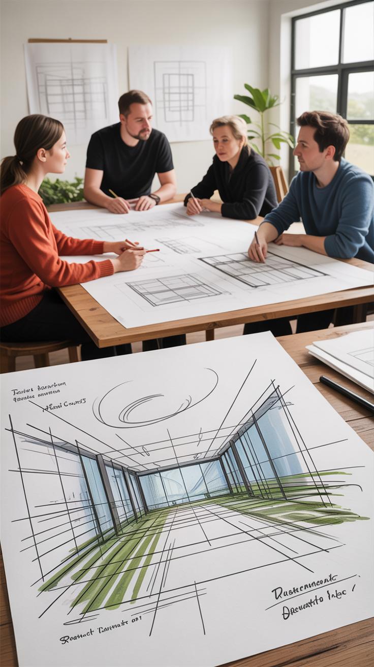
Multiple disciplines rely on a common language, and drawings are it. Engineers, contractors, interior designers — they all read from the same sheet when the drawings reflect clear, coherent details. This reduces miscommunication, but it’s not foolproof. Some drawings can be too dense or too vague, leading to back-and-forth that slows progress.
In practice, I’ve seen how well-crafted drawings speed up coordination. Site teams grasp what’s next and what depends on their work because drawings clarify sequencing and interfaces. Still, you might wonder: how much detail is enough? Balancing precision without overwhelming is a learned skill, but it pays off in smoother teamwork—and maybe fewer headaches down the line.
Conclusions
Mastering the core principles of architectural drawing enables you to create clear, precise, and meaningful representations of your designs. These drawings serve as a vital tool in the architectural process from concept to construction. By following established conventions and focusing on accuracy, you ensure your ideas are communicated effectively to clients, builders, and collaborators.
Applying these principles consistently will enhance your ability to portray complex structures clearly and will support successful project outcomes. Your architectural drawings will become a powerful extension of your creative and technical skills, allowing you to build confidence and credibility in your designs.